How to create your app
Follow this tutorial to learn how to develop an app for MEDUSA© Platform.
For MEDUSA© Platform v2022
If you have any questions that are beyond the scope of this help file, please feel free to ask for help in the forum or contact with us.
- Having the latest version of
MEDUSA© Platform v2022installed - Intermediate to advanced level of Python programming
- Shallow understanding of concurrent programming with threading and multiprocessing Python modules
- Intermediate level of graphic user interfaces development with PyQt or Unity
- Motivation!
MEDUSA© apps are the main components of MEDUSA© Platform. These programs can implement a multitude of different experiments while one or more signals are being monitored. For instance, gamified cognitive tasks, visual stimulation paradigms or brain-computer interfaces (BCI) are just some examples. The limit is your imagination!
There is a wide range of MEDUSA© apps already available in our App Market. Before thinking about creating your own project, we encourage you to check it out carefully.
In this hands-on tutorial you will learn the basics to develop your own app from scratch for MEDUSA© Platform. After completing this tutorial, you will know:
- What is an app: definition and main characteristics
- The workflow and internal states of an app
- The architecture and main components of an app
- Use case: create a new MEDUSA© app based on PyQt
- Use case: create a new MEDUSA© app based on Unity
What's an app?
MEDUSA© apps are programs that facilitate the implementation of open- and closed-loop systems where:
- The participant has an objective: to control a BCI, to perform a cognitive task, etc
- One or more biological signals are being recorded: electroencephalography (EEG), electrocardiography (ECG), electromyography (EMG), electrooculography (EOG), functional near-infrared spectroscopy (fNIRS), etc
- High-precision synchronization is important to identify events in the recordings
MEDUSA© apps have a predefined architecture and workflow that allows to implement any experiment that meet the previous characteristics in the shortest time possible. MEDUSA© Platform is especially designed for researchers, clinicians and companies that are exploring different ideas and need a very flexible environment. In the jargon of BCI-related publications, an app is usually the equivalent of a BCI paradigm.
In the next subsections of this tutorial, we will deepen into some of the technical characteristics of MEDUSA© apps that you need to know to develop your project.
Workflow and internal states
In order to facilitate the development of new apps, MEDUSA© Platform has a predefined workflow with some rules that must be followed.
First, all apps must have the same possible range of internal states defining their lifecycle, which is represented by two variables:
app_state, which represents the state of the app by changing among four possible values:OFF,POWERING ON,POWERING OFFandON. An app isOFFwhen it has not been launched yet. An app isONwhen is prepared to start a run. The remaining states are the transitions between theONandOFFstates.run_state, which represents the state of each run. This variable can take five possible self-explanatory values:READY,RUNNING,PAUSED,STOPandFINISHED.
The variables app_state and run_state are objects of type multiprocessing.Value. Therefore, the value is shared across all threads and processes in the lifecycle of the app. Of note, you can check and change the value of these states from any part of the app code. Please, read the next section for more details.
The following figure shows the lifecycle of an app run:

MEDUSA© Platform. **This state is reached automatically whenever a run ends (e.g., an oddball paradigm with 100 stimuli). If a run has not a defined end, but is the user who must stop the app, this state will not be reached.
Architecture and main components
MEDUSA© apps have a predefined architecture with standard components to facilitate the implementation of custom experiments. The most important ones are:
-
App class. This class, which must inherit fromresources.AppSkeleton, is the central component of a MEDUSA© app. It implements the main workflow of the app, which executes the following tasks: (1) first, it sets up all the child threads required for an app, including LSL workers, the manager thread, and optional communication threads; (2) then, it executes the graphic interface, blocking the process until the graphic interface is closed; and (3) finally, it closes the auxiliary threads and liberates all the resources to finish execution. -
LSL workers. For each LSL stream of the MEDUSA© working environment, theAppprocess creates a thread that listens for new incoming data from the stream. Each LSL worker keeps the data of the corresponding stream, which can be accessed via thread-safe functions from all other application threads. -
Manager thread. This thread waits for events from the graphical interface. Once an event is received, it handles it by running the appropriate tasks. It also has access to the data of the LSL workers in case the interface requires any signal processing tasks (e.g., power in theta band of an EEG in a neurofeedback experiment). -
Graphic interface. It implements the graphic interface code and experiment flow with a blocking method that returns only when the task is done. It may be necessary to create auxiliary threads to control the experiment flow. Currently, MEDUSA© supports graphic interfaces based on PyQt5 ( written in Python) or on the Unity engine (written in C#). -
Communication interface. This interface implements the communication protocol between thegraphic interfaceand themanager threadto control the workflow of the application. Depending on the graphic interface that we are using (PyQt or Unity), the communication interface changes substantially. See the following sections to know more about this. -
Settings class. This class, which must inherit frommedusa.components.SerializableComponent, holds the configuration information of the app (e.g., number of runs and trials, etc).
Create your app project
Now that you are familiar with the main components of a MEDUSA© app, it is time to create your own project. To proceed, follow these steps:
- Open
MEDUSA© Platform. - In the menu bar, go to the developer tools section and click on
"Developer tools/Create app". - Choose the
app ID. This identifier cannot contain spaces or special characters (only letters and numbers). For this example, you can write "tut". - Choose the
app name. The app name has to be a readable descriptive string. For this example, you can write "Tutorial". - Choose the
app template:- Empty project: choose this option if you want to start an app from scratch (not recommended) or if you plan to copy the files of an existing app and modify the content. Regarding the latter, you must ensure first that your actions comply with the app license or legal actions could be taken.
- Qt project: choose this option if you want to develop an app with a graphic interface based on PyQt5. This option is adequate for protocols with simple graphic interfaces where temporal requirements are not critical, taking into account that these projects are easier to develop than Unity projects. This option creates a project containing a ready-to-use example of a PyQt5-based MEDUSA© app that you can modify at will to build your own project.
- Unity project: choose this option if you want to develop an app with a graphic interface based on Unity. This option is adequate for gamified protocols where temporal requirements are critical (i.e., you need to control exactly the refreshed frames and/or the monitor refresh rate), taking into account that these projects require more expertise than PyQt5 projects. This option creates a project containing a ready-to-use example of a Unity-based MEDUSA© app that you can modify at will to build your own project.
To start coding, open the project in your preferred Python IDE (we recommend PyCharm). Use the folder "src" in your MEDUSA© Platform installation folder as the root of the project. Then, navigate to the app folder in accounts/<username>/apps/<app id>. The files inside include:
-
main.pyThis file contains the code of theApp class, which implements the main process, theLSL workersand themanager thread. Here you will have to implement tasks that are not related to the graphic interface, such as signal processing algorithms. settings.pyThis file implements theSettings classof the app with all the configuration options.app_constants.pyThis optional file contains any constant that may be necessary for the app.-
requirements.txtThis file contains the packages that the app requires to be executed and that are not already included in the requirements.txt file of theMEDUSA© Platformroot directory. LICENSEThe license is the legal instrument governing the use or redistribution of the app.icon.pngThe icon, in PNG format, that will be displayed in the platform's app panel.Graphic interface filesFiles with the graphic interface implementation, which depend on the framework used to develop the app. We will explain more about these files in the following sections of the tutorial.
In the next sections, we will show you how to use both PyQt5 and Unity templates to design your own apps with a guided example: a simple neurofeedback experiment with EEG. If you selected the PyQt5 project, continue with the next section. If you selected the Unity project, jump here.
Develop a PyQt-based app
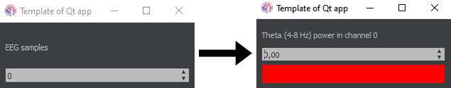
In this example, we will modify the PyQt5 template, which counts the received samples of an EEG signal, to implement a simple neurofeedback experiment that calculates EEG theta-band power in the first channel and displays the value using a color-based feedback. For simplicity, follow this tutorial to create a fake EEG signal first.
As we aim at offering the theta-band power as feedback, we need to get rid of the default graphical user interface (GUI) and customize it to display: (1) the absolute theta-band power value, and (2) the color we want to show as feedback. What we want to obtain is shown in the following figure.
To start with these modifications, first open app_gui.py, which implements the graphic interface functionalities. In the AppGui class constructor, substitute lines 54 to 65 with the following block of code:
                        # Label
self.label = QtWidgets.QLabel('Theta power in channel 0')

# Spin box
self.spin_box = QtWidgets.QDoubleSpinBox()
self.spin_box.setMinimum(0)
self.spin_box.setMaximum(9999999)
self.spin_box.setValue(0)

# Color label
self.color_label = QtWidgets.QLabel('')
self.color_label.setStyleSheet("background-color: red")

# Add widgets
self.main_layout.addWidget(self.label)
self.main_layout.addWidget(self.spin_box)
self.main_layout.addWidget(self.color_label)
As shown, this block of code creates all necessary widgets to create the target GUI. In this case, we only require to use objects of type QLabel (to display one-line text) and QDoubleSpinBox (to display decimal numbers). Note that the color is coded using an empty QLabel and modifying its CSS style to change the color of the background by using the method setStyleSheet(). Finally, it is required to add all of these new widgets to the main layout, which sorts all items vertically.
Next, change the definition of update_response_signal in AppGuiWorker class (line 130) to:
update_response_signal = pyqtSignal(float)
This line of code creates a pyqtSignal that allows, together with a pyatSlot, to update the GUI whenever a new float value is computed. Note that this value will be our theta-band power!
Finally, change the update_response_handler method:
                        @pyqtSlot(float)
def update_response_handler(self, value):
 self.spin_box.setValue(value)
 if value > self.app_settings.power_threshold:
  self.color_label.setStyleSheet("background-color: green")
 else:
  self.color_label.setStyleSheet("background-color: red").
This method will be called whenever we want to update the GUI using a new computed theta-band power value. As shown, we are toggling the background of the QLabel between green (if the current power is greater than a default threshold) or red (otherwise).
Now go to main.py to implement the signal processing method to calculate the power in theta band (4-8 Hz). To do so, we are going to use two functions that are already included in MEDUSA© Kernel. First, import these functions:
                        from medusa.transforms import power_spectral_density
from medusa.local_activation.spectral_parameteres import absolute_band_power
Next, find the method process_event and substitute the code of the "update_request" event (lines 89 to 94):
                        # Calculate theta power
self.queue_to_gui.put({
 'event_type': 'update_response',
 'data': self.calculate_theta_power()
})
Here we are sending the theta power through a multiprocessing.Queue. This value will be received by the GUI. Note that we have not defined the signal processing function yet!
To fix this issue, add the method calculate_theta_power to the App class:
def calculate_theta_power(self):
    # Get lsl worker and sample rate
    lsl_worker = self.get_lsl_worker()
    fs = lsl_worker.receiver.fs
    # Get the signal of the last 10 seconds from channel 0
    signal = lsl_worker.data[int(-fs * 10):]
    # Calculate power spectral density
    f, psd = power_spectral_density(signal, lsl_worker.receiver.fs)
    # Calculate power in theta. Returns dimensions of [epochs x channels]
    theta_power = absolute_band_power(psd, fs, [4, 8])
    # Select epoch 0 and channel 0
    theta_power_cha_0 = theta_power[0, 0]
    return theta_power_cha_0
Our signal processing method first takes the current LSL worker, which by default is the fake EEG signal that we are streaming via LSL. Then, we compute the power spectral density (PSD) of the last 10 seconds of the first channel. Finally, we compute the absolute band power in theta band (between 4 and 8 Hz), and return the value.
Finally, open settings.py to define the value of the threshold that controls the color of the feedback. To do so, just change the class constructor:
                        def __init__(self, updates_per_min=60, power_threshold=0.04):
 self.updates_per_min = updates_per_min
 self.power_threshold = power_threshold
Congratulations! You've implemented a new PyQt5-based application. In the process, you have seen how the PyQt5 template can be modified to build your own project. Of course, this is only the beginning. For more advanced projects you will need to modify more parts of the template and get a better understanding of the rest of components. Please, use the forum if you have any doubts!
Develop a Unity-based app
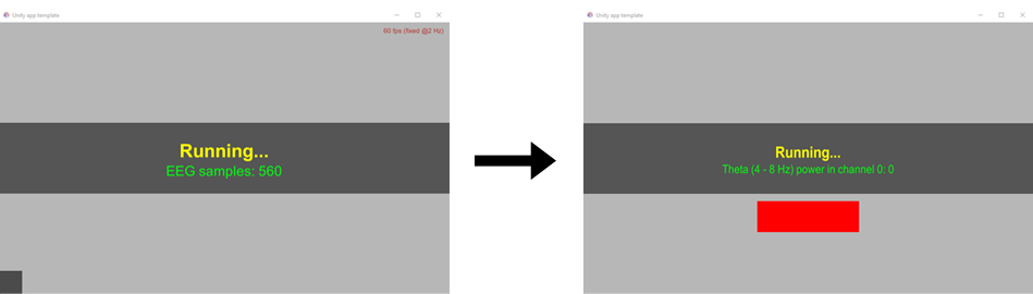
In this example, we will modify the PyQt5 template, which counts the received samples of an EEG signal, to implement a simple neurofeedback experiment that calculates EEG theta-band power in the first channel and displays the value using a color-based feedback. For simplicity, follow this tutorial to create a fake EEG signal first.
Once unzipped, it is time to open the project app-demo-unity-src. For this it is necessary to have the Unity editor installed. The files inside include a directory called Scripts. This directory contains the following files:
-
LogToFile.cs:this file contains the code of theLogToFile class. It takes every single message sent as Debug.Log() and writes it to a file. This script must not be modified. Manager.cs:this is the main file of the Unity project. It controls the lifecycle of the client side of the MEDUSA© app. In addition, it creates an instance of theMedusaTCPClient classto report the status of the app to the MEDUSA© server side (i.e., MEDUSA© Platform). This script has an extensive description of each of the elements that compose it and its functions. It is strongly recommended to read and understand it before modifying it.MedusaTCPClient.csthis file implements theMedusaTCPClient class, which establishes connection with the TCP server instantiated in MEDUSA© Platform. Therefore, it allows the app to receive and send messages to MEDUSA© Platform asynchronously. This script must not be modified.-
MessageInterpreter.csthis file defines theMessageInterpreter class, whose purpose is to decode the various messages sent from the server side of the app. This script will have to be slightly modified to prepare it for the different messages sent from the server.
First, we will make changes to the graphical user interface, as shown in the following figure.
- For the color bar, add an Image element in Canvas. Then modify the dimensions to make it look rectangular and change its color to red. We called this element Color_label.
- Disable the Photodiode Cell and FPSmonitor elements by unchecking the check box that appears in the inspector when selecting them. These items are useful to check the refresh rate of our app in applications that require a precise stimulation rate, such as apps based on c-VEPs. However, they will not be necessary in our neurofeedback app.
- Finally, modify CounterText, inside InformationBox. We will use this text to indicate the Theta power of Channel 0, instead of as a sample counter. We have renamed this element as PowerText.
Now it is time to modify the Manager.cs file. First, replace the counterText object with powerText on lines 100 and 132. Next, rename the setCounterText function to setPowerText and replace the calls to the counterText object with powerText as follows:
                          void setPowerText(string infoMsg)
{
  if (string.IsNullOrEmpty(infoMsg))
  {
   powerText.SetActive(false);
  }
  else
  {
   powerText.SetActive(true);
   powerText.GetComponent().text = infoMsg;
  }
}
Remember to replace the setCounterText function call with setPowerText on lines 200, 215 and 360. Now replace the boolean parameter mustUpdateSamples by mustUpdatePower in lines 87, 212, 216 and 327. This parameter will be used to determine when to update the power display and the color bar
Substitute the variable no_samples for theta_power in lines 97, 215 and 328:
                          // Other attributes
...
public float theta_power = 0;

if (mustUpdatePower)
{
  setInformationText("Running...");
  setPowerText("Theta (4-8 Hz) power in channel 0: " + theta_power.ToString();
  mustUpdatePower = false;
}

case "samplesUpdate":
  mustUpdatePower = true;
  theta_power = messageInterpreter.decodeSamples(message);
  break;
Now we are going to introduce the code that controls the Color label. This will be colored red by default, and will turn green when the Theta power exceeds a certain threshold. To do this, modify the code in the following lines: 98, 101 - 103 and 132:
                          // Other attributes
...
public float power_threshold = 0;
...
private GameObject informationBox, informationText, powerText, colorLabel;
public Color defaultBoxColor = new Color(255f/255, 30f/255, 30f/255, 30f/255);
public Color highlightBoxColor = new Color(30f/255, 255f/255, 30f/255,30f/255);

// Find the colorLabel object
colorLabel = GameObject.Find("Color_label");
Once the colorLabel object and the power_threshold are defined, add the following lines to control the color of the bar in the line 209:
                          if (mustUpdatePower)
{
  setInformationText("Running...");
  setPowerText("Theta (4-8 Hz) power in channel 0: " + theta_power.ToString();
  if (theta_power > power_threshold)
  {
   colorLabel.GetComponent().color = highlightBoxColor;
  }
  else
  {
   colorLabel.GetComponent().color = defaultBoxColor;
  }
  mustUpdatePower = false;
}
Finally, we are going to have Unity request a Theta power update from MEDUSA© based on the updates_per_min parameter. To do so, modify the code inside FixedUpdate function as follows:
                        void FixedUpdate()
{
  if (state == RUN_STATE_RUNNING)
  {
      ServerMessage sm = new ServerMessage("request_update")
      tcpClient.SendMessage(sm.ToJson());
      fixedUpdateCount = 0;
  }
}
Now go to app_controller.py to prepare the application to receive the "request_update" message from the Unity client. To do this, replace "request_samples" with "request_update" in line 163. It will also be necessary to add the new parameter "power_threshold" to be sent. To do this, add the following to the send_parameters function on line 82:
                          def send_parameters(self)
print(self.TAG, "Setting parameters...")
msg = dict()
msg["event_type"] = "setParameters"
msg["updates_per_min"] = self.app_settings.run_settings.updates_per_min
msg["power_threshold"] = self.app_settings.run_settings.power_threshold
self.send_command(msg)
The next step is to implement the signal processing method to calculate the power in the theta band (4-8 Hz) in main.py. First, import these functions:
                          from medusa.transforms import power_spectral_density
from medusa.local_activation.spectral_parameteres import absolute_band_power
Next, find the method process_event and substitute the code of the "request_samples" event (lines 238 to 244):
                          if event["event_type"] == 'request_update':
lsl_worker = self.get_lsl_worker()
self.app_controller.send_command({
 'event_type': 'update_response',
 'data': self.calculate_theta_power()
})
Add the method calculate_theta_power to the App class:
                          def calculate_theta_power(self):
 # Get lsl worker and sample rate
 lsl_worker = self.get_lsl_worker()
 fs = lsl_worker.receiver.fs
 # Get the signal of the last 10 seconds from channel 0
 signal = lsl_worker.data[int(-fs * 10):]
 # Calculate power spectral density
 f, psd = power_spectral_density(signal, lsl_worker.receiver.fs)
 # Calculate power in theta. Returns dimensions of [epochs x channels]
 theta_power = absolute_band_power(psd, fs, [4, 8])
 # Select epoch 0 and channel 0
 theta_power_cha_0 = theta_power[0, 0]
 return theta_power_cha_0
Once the server side of the app is ready to receive messages, process the signal and send the information, we will prepare the client side of the app (Unity) to receive and interpret this information. On the one hand, add the following code in MessageInterpreter.cs:
                          public class ParameterDecoder
{
  public int updates_per_min;
  public float power_threshold;
  public static ParameterDecoder getParametersFromJSON(string jsonString)
  {
    ParameterDecoder p = JsonUtility.FromJson<ParameterDecoder>(jsonString);
    return p;
  }
}

public float decodePower(string message)
{
  return DecodePower.getPowerFromJSON(message);
}

public class DecodePower
{
  public float data;
  public static float getPowerFromJSON(string jsonString)
  {
    DecodePower theta_power = JsonUtility.FromJson<DecodePower>(jsonString);
    return theta_power.data;
  }
}
On the other hand, in Manger.cs, replace "samplesUpdate" with "update_response" in the function interpretMessage. It will also be necessary to replace the function for interpreting the theta power information associated with the "update_response" message and OnParametersReady function:
                          public void interpretMessage(string message)
{
  string eventType = messageInterpreter.decodeEventType(message);
  swtich (eventType)
  {
  ...
   case "update_response":
   mustUpdatePower = true;
   theta_power = messageInterpreter.decodePower(message);
   break;
  ...
  }
}

void OnParametersReady()
{
  updates_per_min = parameters.updates_per_min;
  power_threshold = parameters.power_threshold;
  ...
}
Finally, open settings.py to define the value of the threshold that controls the color of the feedback. Change the attributes of RunSettings class:
                          class RunSettings:
def __init__(self, updates_per_min=60, power_threshold=0.04):
 self.updates_per_min = updates_per_min
 self.power_threshold = power_threshold
Once everything is modified and you have checked that it works correctly, create the Unity executable file using the Build Settings option. Create the executable in a separate folder and then paste the contents into the unity folder of your app project following the path accounts/<username>/apps/<app id>.
Congratulations! You have already implemented your first MEDUSA© app using Unity. Now, by following these steps, and going deeper into the changes, you will be able to create your own MEDUSA© apps. Do not hesitate to contact us if you have any questions, problems or suggestions.
Distribution and intellectual property
The distribution terms are specified in our App Distribution License Agreement (ADLA).
Authors are allowed to distribute their MEDUSA© apps through the official app market only. Note that the ADLA includes the possibility of making an app public (available to all users), or private (available only to authorized users).
Authors hold the intellectual property of their apps. Distribution and commercialization is permitted under our ADLA. It is important to highlight that the Biomedical Engineering Group of the University of Valladolid holds the intellectual property of MEDUSA© Platform and MEDUSA© Kernel, but declines any right regarding third-party apps.